M‑type Thrust Self-Aligning Roller Bearings
The M-type thrust self-aligning roller bearings feature a turned solid brass cage structure, providing excellent overall rigidity. Combined with spherical drum rollers and precision-machined spherical raceways, they offer outstanding self-aligning capabilities. This design effectively compensates for shaft misalignment, installation misalignment, and deflection caused by equipment operation, thereby preventing premature failure due to stress concentration at the roller edges. These bearings are primarily designed to withstand extremely high axial loads while also accommodating partial radial loads. They perform exceptionally well under harsh operating conditions such as low speeds, heavy loads, severe shocks, high temperatures, and intense vibration. The brass cage offers excellent toughness, wear resistance, and heat resistance, making it resistant to deformation or fracture. It effectively ensures smooth roller operation, reduces friction loss and abnormal wear, and significantly enhances the bearing’s overall service life and operational reliability. Although its maximum operating speed is lower than that of the E-series with stamped steel cages, it offers significant advantages in load-carrying capacity, impact resistance, and structural stability. It is capable of withstanding the demanding conditions of prolonged continuous operation and is widely used in large industrial equipment requiring high axial load-carrying capacity and operational stability, such as vertical mills, heavy-duty cranes, metallurgical rolling mills, marine equipment, petroleum machinery, extruders, and heavy-duty mining equipment—all of which demand extremely high axial load-bearing capacity and operational stability. It serves as a critical core bearing component for withstanding heavy thrust loads under extreme operating conditions.
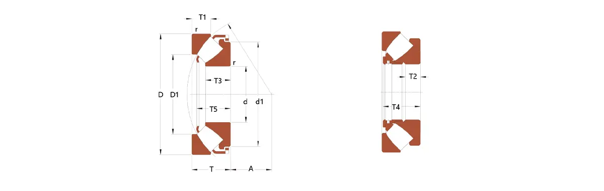
Product Parameters
| Inquiry | Model | Basic Dimensions (mm) | Rated Load (kN) | Limiting Speed (r/min) | Weight ≈kg |
||||
|---|---|---|---|---|---|---|---|---|---|
| model | d | D | B | C Dynamic | C0 Static | Ref. | Lim. | ||
| ✉️ | 29248M | 240 | 340 | 60 | 1010 | 4150 | 1060 | 1890 | 16.9 |
| ✉️ | 29348M | 240 | 380 | 85 | 2040 | 6500 | 880 | 1710 | 32.8 |
| ✉️ | 29448M | 240 | 440 | 122 | 3600 | 10500 | 740 | 1470 | 74.1 |
| ✉️ | 29252M | 260 | 360 | 60 | 1040 | 4550 | 970 | 1780 | 17.6 |
| ✉️ | 29352M | 260 | 420 | 95 | 2550 | 8300 | 790 | 1540 | 45.8 |
| ✉️ | 29452M | 260 | 480 | 132 | 4400 | 13200 | 660 | 1350 | 96.6 |
| ✉️ | 29256M | 280 | 380 | 60 | 1020 | 4700 | 900 | 1670 | 19 |
| ✉️ | 29356M | 280 | 440 | 95 | 2650 | 8800 | 740 | 1460 | 49.1 |
| ✉️ | 29456M | 280 | 520 | 145 | 5200 | 15800 | 600 | 1230 | 126 |
| ✉️ | 29260M | 300 | 420 | 73 | 1400 | 6200 | 830 | 1500 | 29.9 |
| ✉️ | 29360M | 300 | 480 | 109 | 3200 | 10500 | 680 | 1320 | 65.1 |
| ✉️ | 29460M | 300 | 540 | 145 | 5200 | 16200 | 570 | 1180 | 130 |
| ✉️ | 29264M | 320 | 440 | 73 | 1410 | 6500 | 780 | 1420 | 31.6 |
| ✉️ | 29364M | 320 | 500 | 109 | 3350 | 11000 | 650 | 1260 | 72.4 |
| ✉️ | 29464M | 320 | 580 | 155 | 6000 | 19100 | 530 | 1090 | 163 |
| ✉️ | 29268M | 340 | 460 | 73 | 1410 | 6600 | 740 | 1350 | 33.3 |
| ✉️ | 29368M | 340 | 540 | 122 | 3750 | 12600 | 600 | 1150 | 101 |
| ✉️ | 29468M | 340 | 620 | 170 | 7200 | 23100 | 475 | 1020 | 208 |
| ✉️ | 29272M | 360 | 500 | 85 | 1870 | 8500 | 690 | 1230 | 49 |
| ✉️ | 29372M | 360 | 560 | 122 | 3750 | 13000 | 570 | 1110 | 105 |